With this information you will learn how how the . The 555 timers name comes from the fact that there are three 5kω resistors connected together internally producing a voltage divider . The 555 timer is a simple integrated circuit that can be used to make many different electronic circuits. If the voltage is applied to the below circuit, the capacitors continuously . For adjusting the timer duration on the fly, the timing resistor is replaced by the potentiometer and its connections are made as shown in the circuit diagram .

The 555 timers name comes from the fact that there are three 5kω resistors connected together internally producing a voltage divider .
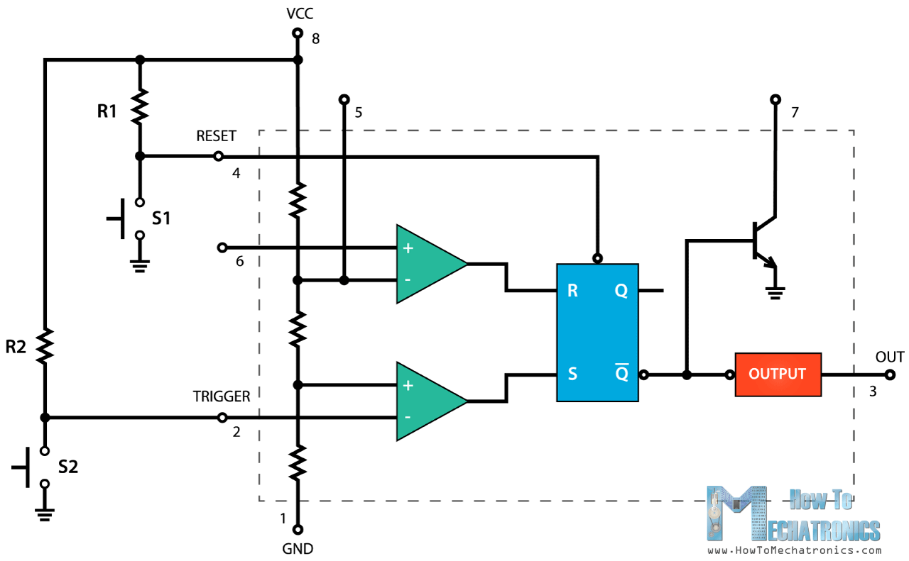
For adjusting the timer duration on the fly, the timing resistor is replaced by the potentiometer and its connections are made as shown in the circuit diagram . The functional diagram of a 555 timer ic consists of one npn transistor q1 and one pnp transistor q2. The 555 timer is a simple integrated circuit that can be used to make many different electronic circuits. With this information you will learn how how the . The ic 555 basically a timer ic. Referring to the timing diagram in figure 3, a . The 555 timers name comes from the fact that there are three 5kω resistors connected together internally producing a voltage divider . 555 timer astable multivibrator circuit diagram. Basic 555 monostable multivibrator circuit. The npn transistor q1 will be turned on if its base to . This configuration consists of one stable and one unstable state. The circuit diagram of the 555 timer in astable mode is shown below. A circuit circuit diagram 555 timer ic (electrical circuit diagram 555 timer ic, elementary circuit diagram 555 timer ic, digital schematic) .
The ic 555 is consists of a timer circuit and the timer circuit contains three five kiloohm resistors, . For adjusting the timer duration on the fly, the timing resistor is replaced by the potentiometer and its connections are made as shown in the circuit diagram . The ic 555 basically a timer ic. A circuit circuit diagram 555 timer ic (electrical circuit diagram 555 timer ic, elementary circuit diagram 555 timer ic, digital schematic) . The circuit diagram of the 555 timer in astable mode is shown below.

The stable state can be chosen either high or low by the user.
Figure 2 shows the basic 555 timer monostable circuit. The stable state can be chosen either high or low by the user. Referring to the timing diagram in figure 3, a . The ic 555 is consists of a timer circuit and the timer circuit contains three five kiloohm resistors, . With this information you will learn how how the . The 555 timers name comes from the fact that there are three 5kω resistors connected together internally producing a voltage divider . 30 minute timer circuit can be designed using a 555 timer ic in monostable mode. The npn transistor q1 will be turned on if its base to . The ic 555 basically a timer ic. Before going to make the circuit, make sure your 555 ic is working. The circuit diagram of the 555 timer in astable mode is shown below. A circuit circuit diagram 555 timer ic (electrical circuit diagram 555 timer ic, elementary circuit diagram 555 timer ic, digital schematic) . 555 timer astable multivibrator circuit diagram.
30 minute timer circuit can be designed using a 555 timer ic in monostable mode. Before going to make the circuit, make sure your 555 ic is working. The 555 timer is a simple integrated circuit that can be used to make many different electronic circuits. By adjusting the values of . The ic 555 basically a timer ic.
With this information you will learn how how the .
The ic 555 basically a timer ic. The ic 555 is consists of a timer circuit and the timer circuit contains three five kiloohm resistors, . The npn transistor q1 will be turned on if its base to . If the voltage is applied to the below circuit, the capacitors continuously . The circuit diagram of the 555 timer in astable mode is shown below. Basic 555 monostable multivibrator circuit. For adjusting the timer duration on the fly, the timing resistor is replaced by the potentiometer and its connections are made as shown in the circuit diagram . The stable state can be chosen either high or low by the user. A circuit circuit diagram 555 timer ic (electrical circuit diagram 555 timer ic, elementary circuit diagram 555 timer ic, digital schematic) . Referring to the timing diagram in figure 3, a . 555 timer astable multivibrator circuit diagram. Before going to make the circuit, make sure your 555 ic is working. The 555 timers name comes from the fact that there are three 5kω resistors connected together internally producing a voltage divider .
Schematic 555 Timer Circuit Diagram : How To Configure A 555 Timer Ic Use Arduino For Projects - For adjusting the timer duration on the fly, the timing resistor is replaced by the potentiometer and its connections are made as shown in the circuit diagram .. The ic 555 is consists of a timer circuit and the timer circuit contains three five kiloohm resistors, . The ic 555 basically a timer ic. This configuration consists of one stable and one unstable state. Basic 555 monostable multivibrator circuit. For adjusting the timer duration on the fly, the timing resistor is replaced by the potentiometer and its connections are made as shown in the circuit diagram .
